C13 to C14 Power Cable Selection Guide: 10A/16A Power Matching and Data Center PDU Deployment Best Practices
What do data center engineers fear most? Not server outages, but discovering after a PDU trips that the C13-to-C14 power cable was incorrectly specified. A 10A-rated cable forced to handle a 16A load causes overheating and melting at connection points, potentially leading to service interruptions or even fires. This article begins with the IEC 60320 standard, breaking down the power limits of 10A vs. 16A, the logic behind wire gauge matching, and practical tips for avoiding pitfalls during PDU deployment in data centers, helping you select the right C13-to-C14 power cable on your first try.
Basic Understanding and Standard Interpretation of C13-to-C14 Power Cables

IEC 60320 is a globally recognized standard developed by the International Electrotechnical Commission for appliance couplers. As one of the most widely used combinations, C13/C14 serves as the power connection between servers, switches, storage devices, and PDUs. C13 is the female connector (device end), while C14 is the male connector (power source end). The two achieve a reliable connection through a snap-lock mechanism, and the anti-misconnection design is especially important in densely packed cabinet environments.
IEC 60320 Interface Specifications and Physical Characteristics of C13/C14
The C13/C14 connector features a three-pin design: live wire (L), neutral wire (N), and protective earth (PE). The standard operating voltage is 250V AC, compatible with frequencies of 50/60Hz. The connector housing is made of flame-retardant engineering plastic, typically with a temperature resistance exceeding 70°C. Pin spacing and outline are precisely calculated to ensure physical interlocking with C15/C16 (high-temperature version) and C19/C20 (high-current version), preventing incorrect insertion.
Structural Differences and Identification Markings Between 10A and 16A Versions
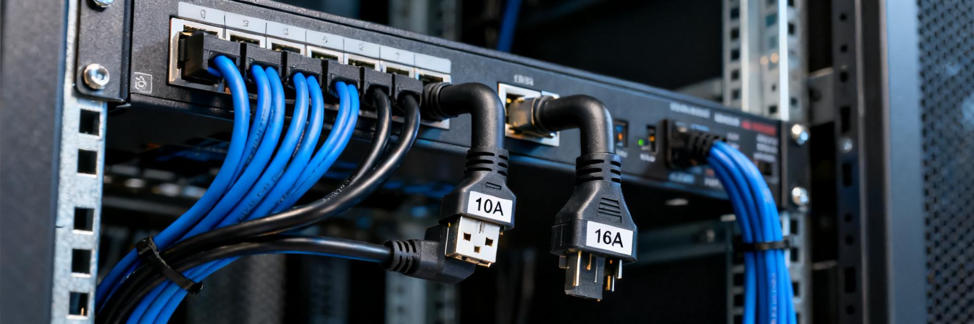
The core differences between the 10A and 16A versions lie in the cross-sectional area of the conductive busbar and the heat dissipation structure. The 16A version features wider sockets and greater spring contact pressure, resulting in lower contact resistance. Quick identification method: check the molded marking on the plug—labels such as "10A 250V~" or "16A 250V~" are typically located on the top or side of the plug. Additionally, the C14 male pins on the 16A version are slightly thicker, providing a tighter feel when inserted, which directly reflects the reinforced spring design.
| Parameter Item | 10A Version | 16A Version |
|---|---|---|
| Rated Current | 10A | 16A |
| Maximum Power at 250V | 2500W | 4000W |
| Recommended Minimum Wire Gauge | 0.75mm² | 1.5mm² |
| Typical Application Scenarios | Single-Power Supply Servers, Switches | Dual-Power Supply Servers, Blade Centers |
Core of Power Matching: Sizing Calculations for 10A and 16A
Power matching is the fundamental principle for selecting C13-to-C14 power cords. Ignoring current limits renders all subsequent design efforts futile.
Power handling limits at 250V (2500W vs 4000W)
According to P=U×I, at 250V, the theoretical maximum power is 2500W for the 10A version and 4000W for the 16A version. However, in practical deployments, power factor (PF) and harmonic effects must be considered: resistive loads can be calculated at full capacity, while inductive loads should account for a 10%-15% margin. For a dual-power server rated at 800W, with each rail drawing about 400W under full load, a 10A cable might seem sufficient; yet, factoring in power supply inrush currents (typically 1.5–2 times the rated value) and aging degradation, the 16A version remains the safer choice.
Conversion Formula for Server Rated Power and Cable Selection
Practical Conversion Process: First, confirm the equipment nameplate rated power or the maximum power of the power module; second, divide by the voltage to obtain the theoretical current, then multiply by a redundancy factor of 1.25; finally, round up to match the cable specification. For example: 1200W power module → 1200÷250=4.8A → 4.8×1.25=6A → Theoretically, 10A can cover it, but in dual-power concurrent operation or future expansion scenarios, directly selecting the 16A version is more forward-looking.
Redundancy Design and Safety Margin Setting for Peak Current
Data center Tier III and higher levels require N+1 or 2N redundancy, which must be simultaneously followed in cable selection. The key principle is: the current-carrying capacity of a single cable ≥ the maximum power of a single power module × 1.5. This 1.5 factor accounts for extreme conditions such as startup inrush, aging-related temperature rise, and poor ventilation. In cold/hot aisle layouts, if cables pass through hot aisles where ambient temperatures may exceed 35°C, the current rating must be derated by a factor of 0.85–0.9.
Impact of Wire Gauge and Conductor Material on Current Rating
Wire gauge determines the upper limit of current carrying capacity, while material affects conductivity efficiency and long-term stability; together, they form the cable's "vascular system."
Applicable Scenarios for 0.75mm²/1.0mm²/1.5mm² Wire Gauges
The long-term safe current-carrying capacity of 0.75mm² copper wire is approximately 6-8A, making it suitable for low-power network devices or monitoring terminals; however, it has been gradually phased out in main data center power supplies. A 1.0mm² copper wire carries 10-13A and serves as an economical choice for 10A C13-to-C14 power cords, though its temperature rise tends to be relatively high under marginal operating conditions. A 1.5mm² copper wire supports 16-20A, which is the standard configuration for the 16A version and also provides ample thermal redundancy for the 10A version. Selection guideline: choose a larger wire gauge rather than a smaller one; for every 10°C reduction in temperature rise, insulation life doubles.
Performance Comparison and Risk Warning Between Oxygen-Free Copper and CCA (Copper-Clad Aluminum)
Oxygen-free copper (OFC) has a resistivity as low as 0.0172 μΩ·m and excellent oxidation resistance, making it the preferred choice for data center-grade cables. Although CCA (copper-clad aluminum) is 30%–50% cheaper, its aluminum core has a higher resistivity of 0.028 μΩ·m, and the copper-aluminum interface poses a risk of electrochemical corrosion, leading to a sharp increase in contact resistance over time. Measured data shows that, under the same 1.5 mm² specification, after running at a 10 A load for 2 hours, the surface temperature of CCA cables is 8–12°C higher than OFC, with temperature differences at the connectors exceeding 15°C. The use of CCA material is strictly prohibited in data center environments, as it constitutes a critical red-line issue in operations and maintenance audits.
Practical Application of C13-to-C14 Adapters in Data Center PDU Deployment
PDUs represent the "last mile" of power supply in data centers, and the quality of C13-to-C14 power cable deployment directly determines the reliability of this final segment.
Matching Logic Between Cabinet Power Density and PDU Outlet Configuration
The mainstream cabinet power density has increased from 5 kW per cabinet to 15 kW per cabinet or even higher. Taking 10 kW per cabinet as an example, if dual-circuit PDU power supply is used with each circuit handling 5 kW, multiple 16A output ports must be configured, or C19/C20 high-current interfaces should be adopted. The distribution of C13-to-C14 power cords should follow this principle: high-power devices (>1500W) should prioritize using 16A ports, while medium- and low-power devices can be flexibly allocated. It is crucial to avoid connecting multiple high-power servers to adjacent ports on the same PDU to prevent localized overheating.
Cable Heat Dissipation and Cable Management Planning in High-Density Scenarios
When a 42U cabinet is fully loaded, the number of C13-to-C14 power cords can reach 20–40, creating a dense "cable harness heat island." Core cable management strategies include separating high- and low-voltage circuits, routing cables in hot/cold aisles, and reserving ventilation channels. By combining vertical cable management racks with horizontal cable ties, maintain a natural cable bend radius (≥8 times the cable diameter) to prevent sharp bends that could damage conductors. Measurements show that standardized cable management can reduce rear cabinet temperature differences by 5–8°C and decrease PDU port temperature rise by more than 10%.
Hybrid Deployment: Coexistence Strategy for C13/C14 and C19/C20
Large data centers often face mixed requirements for C13/C14 (10A/16A) and C19/C20 (16A/20A). It is recommended to adopt a zoned PDU design: deploy C19/C20 PDUs in the upper part of the cabinet to serve blade servers and high-power storage, while deploying C13/C14 PDUs in the lower part to cover general-purpose compute nodes. When managing mixed cables, use color coding—blue jackets indicate 10A, black indicates 16A, and red indicates C19/C20—to reduce the likelihood of operational errors.
Common Selection Pitfalls and Troubleshooting Guide
Experience often comes from lessons learned; the following misconceptions frequently occur on-site during operations and maintenance.
Hidden Risks and Real-World Cases of Mixing 10A/16A Connectors
Typical misuse: Forcibly inserting a 10A C13 plug into a 16A C14 socket, or vice versa. The 10A plug has thinner pins; when inserted into a 16A socket, the contact area is insufficient, causing contact resistance to spike. Conversely, a 16A plug cannot physically fit into a 10A socket, but some inferior products have tolerances that exceed specifications. A financial data center once experienced prolonged overheating of PDU terminals due to mixed usage, ultimately leading to insulation carbonization and a short circuit, which caused a six-hour outage for an entire cabinet and resulted in direct losses exceeding one million yuan.
Methods for diagnosing abnormal contact resistance and excessive temperature rise
Infrared thermal imagers are powerful tools for troubleshooting: the temperature rise of a C13-to-C14 power cord connector during normal operation should be ≤15°C (relative to ambient temperature). If localized hot spots are detected, follow these diagnostic steps: first, ensure the plug is fully inserted and hear the locking click; second, inspect the plug pins for oxidation or burn marks; third, measure the circuit resistance (which should normally be <50 mΩ); finally, if necessary, cut open the cable to verify that the conductor material and wire gauge meet specifications. For preventive maintenance, it is recommended to randomly inspect 10% of in-service cables each quarter and establish records of temperature rise trends.
Procurement Acceptance and Operations Management Checklist
Standardized procedures provide institutional safeguards against human error.
Interpretation of Key Items in Factory Test Reports (Temperature Rise Test, Insertion/Removal Life)
Qualified suppliers shall provide third-party test reports, focusing on two key aspects: temperature rise testing (IEC 60320 requires terminal temperature rise ≤45K) and insertion/extraction life (standard ≥10,000 cycles). Some high-end products additionally provide glow-wire test data (no ignition at 850℃) and ball-pressure test data (no deformation at 125℃). During acceptance, random samples are tested on-site: contact resistance is measured using a micro-ohmmeter, and operating temperature rise is monitored with an infrared thermometer to cross-verify the reported data.
Asset Tagging and Regular Inspection System for Data Center Cabling
Establish a full lifecycle record for cables: Record specifications, batch numbers, and test report IDs upon receipt; attach QR code labels to link to equipment assets during deployment; scan and update status during inspections. Recommended inspection cycles: Class A data centers once per month, Class B once per quarter, with重点 checks on high-load circuits, aging cables (in service over 5 years), and locations with previous temperature rise anomalies. Decommissioned cables must undergo destructive disposal to prevent reuse.
Key Summary
- IEC 60320 Standard Compliance: C13 to C14 power cord selection must strictly match rated currents of 10A/16A; physical markings and structural differences serve as quick identification criteria to prevent incorrect insertion or misuse.
- Power Margin Design: Power thresholds of 2500W and 4000W should be calculated comprehensively based on equipment rated power, inrush current, and ambient temperature, with a recommended redundancy factor of ≥1.5x.
- Material and Wire Gauge Red Lines: Oxygen-free copper 1.5mm² is the standard configuration for the 16A version; CCA (copper-clad aluminum) is strictly prohibited from entering the data center due to risks of electrochemical corrosion and excessive heat.
- PDU Deployment Strategy: Power density zoning, separation of strong and weak currents, and color-coding management are the three pillars ensuring reliable power supply for high-density cabinets.
- Full-Cycle Operations and Maintenance Mechanism: From procurement inspection to tagged routine checks, standardized procedures have been established to incorporate C13-to-C14 power cords into the infrastructure asset management system.
Frequently Asked Questions
Can the 10A version of the C13-to-C14 power cord be used temporarily as a substitute for the 16A version?
Absolutely not. The 10A version's conductor cross-sectional area and heat dissipation structure are designed for 2500W; operating under overload will accelerate insulation aging and cause connector melting, potentially leading to short circuits or fires. In emergencies, reduce the load or replace with compliant cabling instead of taking unnecessary risks.
How do you determine whether an existing data center PDU requires a 10A or 16A C13-to-C14 power cable?
Check the equipment nameplate for its rated power; if a single circuit exceeds 1500W or dual-power concurrent operation is required, select the 16A version. For newly deployed equipment, it is recommended to uniformly reserve for 16A to allow room for future power increases and avoid repeated cabling work.
How can you visually distinguish between oxygen-free copper and CCA material C13-to-C14 power cables?
Cut open the cable and examine the cross-section: oxygen-free copper appears uniformly purplish-red and has a soft texture; the CCA cross-section reveals a silvery-white aluminum core that is prone to breaking when bent. A safer approach is to require suppliers to provide material certifications and third-party test reports, and to conduct random sampling and cross-sectional inspection during acceptance.
What is the reasonable service life of a C13-to-C14 power cable?
Under standard data center conditions (temperature 25°C, humidity 40%-60%), high-quality oxygen-free copper cables are recommended to be replaced every 5-7 years. If inspections reveal sheath hardening and cracking, connector discoloration or deformation, or temperature rises exceeding 20°C, the cables should be replaced immediately, regardless of age.
In high-density cabinets, excessive C13-to-C14 power cords make cable management difficult—how can this be resolved?
Prioritize using short-length cables (0.5m–1m) to reduce excess length; introduce angled plugs (90° bends) to minimize space usage; deploy smart PDUs for port-level monitoring to accurately identify overburdened circuits; in extreme scenarios, consider busbar trunking systems as an alternative to traditional PDU solutions.