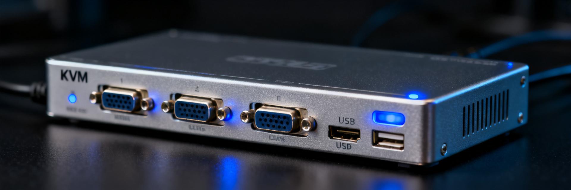
GLCLHSMDST Optical Module Technical Specifications: Comprehensive Analysis, Compatibility Guide, and Key Selection Criteria
According to industry data, in the current data center optical module market, link failures caused by specification mismatches account for over 30%, with neglecting compatibility parameters during the selection phase being one of the main contributing factors.GLCLHSMDSTAs a solution widely deployed in specific scenarios, the precise understanding of optical module technical specifications directly affects the cost and reliability of network construction. This article will provide a systematic analysis of technical specifications and selection guidance, covering core parameter breakdown, compatibility verification methods, and practical selection strategies.
GLCLHSMDST: Core Parameter Breakdown of Optical Module Technical Specifications
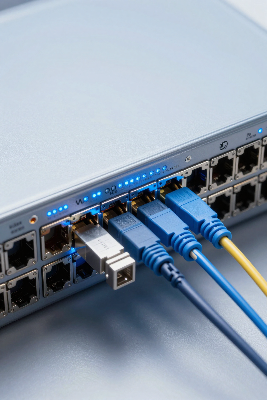
UnderstandingGLCLHSMDSTWhen evaluating optical module technical specifications, it's essential to consider both the package type and the optical interface—these two dimensions together determine whether the module can operate stably within your network environment. Ignoring any single parameter may lead to link jitter or even complete failure after deployment.
Package Type and Electrical Interface Specifications
GLCLHSMDSTIt adopts the standard SFP package form, and its electrical interface complies with the SFP MSA multi-source agreement specification. During verification, you should pay particular attention to confirming that the module's gold finger pin definitions match those of the host-side slot, especially the I²C communication pins and power supply pin layout. Some older switch platforms have SFP slots with differing pin definitions; if not compared in advance, the module may fail to be recognized. In addition, the operating voltage range and power consumption specifications must also be included in the electrical compatibility assessment.
Optical Port Parameters and Transmission Distance Metrics
Optical port parameters directly determine the link budget and transmission distance.GLCLHSMDSTThe center wavelength, spectral width, and emitted optical power must match the receiving sensitivity window of the counterpart module or optical port. When selecting components, you should calculate the overall loss of the fiber optic link, including connector loss, splice points, and fiber attenuation, to ensure that the received optical power remains within the module's sensitivity range. The transmission distance specification is not a single value but is strongly related to the type of fiber (single-mode or multi-mode) and the quality of the link; therefore, it is essential to assess it based on actual field measurements of the fiber.
| Parameter Category | Specific Indicators | Selection Considerations |
|---|---|---|
| Package Type | SFP (Small Form-factor Pluggable) | Confirm the slot depth and gold finger spacing |
| Center Wavelength | Varies depending on the specific sub-model (commonly 1310nm/850nm) | Must be strictly consistent with the wavelength of the peer module |
| Transmission Distance | Short-distance (SR) / Long-distance (LR/ZR) | Calculate loss based on fiber type (single-mode/multi-mode) |
| Operating voltage | 3.3V ± 5% | Check the motherboard's power supply capability and ripple noise |
Compatibility Guide: Key Points for Interoperability Verification of GLCLHSMDST Optical Modules
Compatibility isGLCLHSMDSTthe most easily underestimated aspect in optical module selection. A systematic compatibility guide can help you eliminate most interoperability risks before deployment, avoiding rework costs caused by specification mismatches.
Compatibility matching rules with mainstream switch/router platforms
Different vendors' switch/router platforms have varying mechanisms for recognizing optical modules. When selecting a module, prioritize verifying the platform's requirements for module EEPROM information, including vendor code, module model identification, and checksum format. Some platforms implement strict vendor-locking policies; in such cases, you must confirmGLCLHSMDSTDoes the firmware version of the optical module support the identification protocol of the target platform? It is recommended to conduct small-batch field testing before bulk procurement to verify the module's link establishment and traffic forwarding performance on the target port.
Key Items for Protocol Standards and Interoperability Testing
Interoperability testing should cover three levels: physical-layer link establishment, bit error rate testing, and long-term stability verification. At the physical layer, ensure that the module's signal levels and clock recovery capabilities match those of the peer device; during bit error rate testing, run continuously under full-load traffic conditions to observe whether the BER meets the link requirements; and for long-term stability verification, monitor the module's temperature rise and optical power drift. You can also refer to publicly available industry methods for optical module interoperability testing, create a standardized validation checklist, confirm each item one by one, and then make deployment decisions.
Key Summary
- GLCLHSMDSTThe packaging and electrical interface of the optical module must match the pin definitions of the host slot, with particular attention paid to I²C communication and the layout of power supply pins.
- When selecting optical port parameters, calculate the total link loss to ensure that the received optical power remains within the sensitivity window; determine the transmission distance based on actual fiber optic test data.
- Compatibility verification requires checking the platform's EEPROM identification requirements and confirming link establishment and traffic forwarding performance through small-batch field testing.
- Interoperability testing covers three levels: physical-layer links, bit error rate, and long-term stability. Establishing a standardized verification checklist can effectively mitigate deployment risks.
Frequently Asked Questions
GLCLHSMDSTWhat is the most critical verification item in the optical module compatibility guide?
The most critical verification item is the host platform's requirement for recognizing module EEPROM information. Different switch/router platforms have varying requirements for vendor codes, model identifiers, and checksum formats. If the module firmware does not support the target platform's recognition protocol, it may result in failure to recognize or inability to establish the link. It is recommended to complete small-batch field validation before large-scale deployment.
How to determineGLCLHSMDSTDo the technical specifications of the optical module meet my link requirements?
You need to calculate the overall loss of the fiber optic link, including connectors, splices, and fiber attenuation, then compare the result with the module's transmit optical power and receive sensitivity window. At the same time, confirm that the fiber type matches the module's optical port parameters, and use on-site measured fiber attenuation data to determine whether there is sufficient margin for the transmission distance. It is recommended to maintain a link budget margin of at least 3 dB to account for aging and environmental changes.
GLCLHSMDSTWhat metrics should be monitored during interoperability testing of optical modules?
Interoperability testing should focus on the physical layer link establishment success rate, bit error rate under full load, as well as long-term optical power drift and module temperature rise. The physical layer must verify that signal levels and clock recovery capabilities are compatible with the peer device; bit error rate testing should run continuously under realistic traffic models, and stability verification is recommended to cover the full range of temperature cycling conditions.
Why can't some older switches recognizeGLCLHSMDSToptical modules?
This is typically caused by differences in pin definitions or stringent vendor-locking policies. On older platforms, SFP slots may feature non-standard layouts for I²C communication pins or power pins, or their firmware may only accept EEPROM information with a specific vendor code. To resolve such issues, verify whether the module's firmware version supports the target platform's identification protocol, and perform custom coding if necessary.