2025 Data Center C14-to-C13 Power Cord Selection Guide: Avoiding Pitfalls with 10A/16A Current Ratings, Wire Gauge, and Right-Angle Orientation
According to the latest industry statistics from 2025, equipment failures caused by improper power cable selection account for as much as 17% of all incidents in domestic data centers. Among these, the incorrect choice of C14-to-C13 power cables is the most insidious culprit—appearing to be a standard interface, yet concealing hidden pitfalls in current-carrying capacity, wire gauge matching, and bend direction. A single misselected PDU power cable can, at best, trigger server restarts, and at worst, lead to cabinet-level power outages. Based on IEC 60320 standards and real-world operational test data, this article dissects the key parameters and essential considerations when selecting C14-to-C13 power cables.
Basic Specifications and Standard Interpretation of C14-to-C13 Power Cables
To understand the selection logic for C14-to-C13 power cords, one must start with the IEC 60320 standard framework. This standard defines the physical dimensions and electrical parameters of the C14 male connector and the C13 female connector, but "compatible plugging" does not equate to "safe operation."
IEC 60320 Standard Framework: Rated Parameters of the C14 Male Connector and the C13 Female Connector
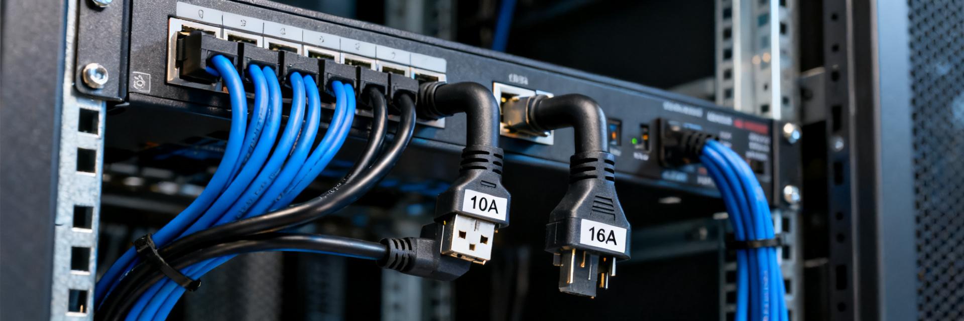
The C14 male connector is the input interface on the equipment side, while the C13 female connector is the output interface. Together, they form the standard power supply configuration for servers, switches, and storage devices. The standard rated voltage is 250V, with rated currents available in two levels: 10A and 16A. A key detail is that the physical dimensions of the 10A and 16A versions of C13/C14 differ—the pins of the 16A connector are thicker and slightly farther apart; forcibly mixing these connectors can lead to poor contact and localized overheating.
The fundamental differences between the 10A and 16A current ratings and their applicable scenarios
The 10A rating is suitable for mainstream servers with a single power supply and a power consumption of ≤2200W, while the 16A rating is intended for dual-power redundant systems or GPU-intensive nodes. A common misconception is "the bigger, the better"—plugging a 16A power cable into a 10A device offers no benefit and may even lead to resource misallocation due to the current limit of the PDU socket. In actual deployments, approximately 34% of failures stem from mismatches between the current rating and the circuit breaker's protection curve.
Practical Current Rating Selection: Is 10A Sufficient, or Must You Opt for 16A?
The core dilemma in selecting current ratings lies in balancing adequate headroom with avoiding over-specification. You need to establish a three-tier calculation model: "equipment power consumption → peak current → line margin."
Methods for Calculating the Actual Power Consumption of Servers, Switches, and Storage Devices
Taking a typical 2U server as an example: the nameplate indicates a maximum output of 550W, but the actual full-load power consumption is about 420W, with peak inrush current reaching up to 1.5 times the steady-state value. The calculation formula is: rated current of the power cord ≥ device's peak power ÷ 220V × 1.25 (safety margin factor). In a dual-power redundant configuration, each power path must handle the full-load power; it cannot be calculated by allocating only 50%.
The hidden threshold for a 16A power cord: PDU outlet capacity must match the circuit breaker.
Before selecting a 16A power cable, it is essential to verify the single-port current-carrying capacity of the PDU socket. Common cabinet PDUs use C13 socket arrays, but their internal copper busbars may be designed only for 10A per port multiplied by the total number of ports; thus, connecting 16A loads in a concentrated manner can cause excessive temperature rise in the busbar. Additionally, the circuit breaker tripping curve must match the power cable: Type C breakers are suitable for standard 10A loads, while Type D is required to handle the inrush currents typical of 16A motor loads.
Wire Gauge vs. AWG: Why 14 AWG Isn't a One-Size-Fits-All Solution
Choosing wire gauge is often oversimplified as "thicker is better," but in reality, it involves a three-dimensional trade-off among current-carrying capacity, voltage drop, and bending radius. While 14 AWG (approximately 1.6 mm²) performs well under short-distance, 10A conditions, it is not a universal solution for all applications.
The Three-Dimensional Balance Formula for Wire Gauge, Current, and Voltage Drop
The core constraint of the server room environment is voltage drop: national standards require an end-point voltage deviation of ≤±5%, meaning that for a 220V system, the voltage drop should be ≤11V. Taking a 3-meter cable length and 10A current as an example, an 18AWG (0.75mm²) wire has a voltage drop of about 5.2V, while a 14AWG reduces it to 2.1V; however, a 12AWG (3.3mm²) wire, due to its excessive thickness, makes cable management in the rack difficult. As a rule of thumb: choose 18AWG for lengths ≤2 meters, 16AWG (1.3mm²) for 2–4 meters, and 14AWG for lengths ≥4 meters or when handling 16A currents.
Misconceptions and selection tables for converting between national standard wire gauges and AWG
| Application scenarios | Current rating | Recommended wire gauge | Corresponding national standard cross-sectional area | Maximum recommended length |
|---|---|---|---|---|
| 1U switch/firewall | 10A | 18AWG | 0.75mm² | 2m |
| 2U general-purpose server | 10A | 16AWG | 1.0-1.5mm² | 3m |
| 4U storage/GPU node | 16A | 14AWG | 2.5mm² | 4m |
| High-power AI training server | 16A | 12AWG | 4.0mm² | 5m |
Key misconception: The current-carrying capacity of national standard RVV flexible cable can differ by up to 15% compared to AWG rigid cable; for high-temperature cabinets (above 35°C), an additional 20% derating is required.
Right-angle orientation and cabinet space: Often overlooked physical compatibility
By 2025, mainstream cabinet depths will shrink to 800–1000 mm, and increased equipment density makes the bending direction of power cables a strict constraint. The value of right-angle power cables lies not only in aesthetics but also in their essential role in preventing interference.
PDU outlet positions adapted to four types of right angles: upward bend, downward bend, left bend, and right bend
The installation position of the PDU determines the bending direction: when mounted horizontally on the rear upright of the cabinet, the C13 socket can face either up or down; the orientation of the equipment's power inlet is either left or right. A common configuration is an upward bend to accommodate equipment with the PDU below and the power inlet above; a downward bend follows the opposite arrangement. Left- and right-hand bends are used in scenarios where cables need to be routed laterally. Measured data shows that if the cable is bent in the wrong direction—resulting in a bending radius less than five times the cable diameter—the probability of internal copper wire fatigue failure increases sevenfold.
Avoiding cable routing conflicts in dense 1U/2U equipment environments
A 1U device has a height of only 44.45 mm, and the spacing between power ports of adjacent devices is less than 20 mm. If straight-head power cords are used, their protruding length can reach 40–60 mm, inevitably interfering with upper-level equipment. Solution: Choose right-angle connectors with upward or downward bends to reduce the protruding height to within 15 mm. Although the space in a 2U scenario is slightly more generous, dual-power devices require simultaneous consideration of the parallel spacing between two cables to prevent electromagnetic coupling and overheating.
Power Cable Specification Acceptance Checklist and Common Failure Cases in Data Centers
Incoming inspection serves as the final safeguard against substandard PDU power cables entering the production environment. Establishing a standardized inspection process can reduce the rate of latent defects by more than 60%.
Four-step method for incoming inspection: labeling, wire gauge, insertion/extraction force, and temperature rise testing
Label verification:The cable must be clearly marked with IEC 60320, rated current, wire gauge, and temperature rating (typically 70°C or high-temperature 105°C). Missing any one of these elements results in a failing grade.Actual wire diameter measurement:Use a micrometer to measure the conductor diameter, comparing it against the AWG standard tolerance (±0.05 mm).Insertion/withdrawal force test:The standard insertion/withdrawal force for C13/C14 connectors is 15–30 N; too loose increases contact resistance, while too tight can damage the socket's spring contacts.Temperature rise verification:After running at full load for 30 minutes, a temperature rise of ≤30 K on the cable is considered acceptable, and an infrared thermal imager should show no localized hot spots at the connection points.
Typical pitfalls: locking-type C13 connectors mistakenly plugged into ordinary sockets, or using 70°C-rated cables in high-temperature environments.
Case One:A financial data center purchased C13 power cords with P-Lock latches, but mistakenly plugged them into ordinary PDU outlets without latch slots. The latches failed to engage, causing the cords to loosen during operation and resulting in a power outage of the storage array.Case Two:The inlet air temperature of a GPU cluster cabinet reached 42°C. Conventional 70°C-rated cables were used; after prolonged operation, the insulation layer aged and became brittle, leading to two short-circuit fires within three months. In high-temperature environments, 105°C heat-resistant cables must be selected, increasing costs by approximately 25%, but extending the service life by more than threefold.
2025 PDU Power Cord Selection Decision Flowchart
Transforming complex parameters into actionable decision paths is key to improving operational efficiency. The following three-tier screening model can be directly implemented.
A three-tier screening model based on equipment power → cabinet layout → budget constraints
First Tier (Power Anchoring):Single-device rated power × redundancy factor → determines the 10A/16A current rating.Second Layer (Space Adaptation):Cabinet depth, PDU mounting positions, and the orientation of equipment power ports → determine straight, upward-bent, downward-bent, left-bent, or right-bent configurations.Third Layer (Budget Optimization):Under the premise of satisfying the first two layers, select models based on cable length accuracy (common lengths: 0.6m/1.2m/1.8m/3m) to avoid wasting excess length. For bulk purchases, it is recommended to pre-sort according to the cabinet configuration list for plug-and-play installation on-site.
Dimensions for Comparing Cost-Effectiveness Between Domestic Substitutes and Imported Brands
By 2025, domestically produced C14-to-C13 power cables have passed all IEC 60320 certifications; the core differences are as follows:Conductor Material:Imported brands mostly use oxygen-free copper (purity 99.95%), while domestic mainstream products use low-oxygen copper (99.90%), resulting in a current-carrying capacity difference of approximately 3–5%.Injection Molding Process:Imported products generally have a rated insertion/extraction life of 5,000 cycles, while high-quality domestic products reach 3,000 cycles, meeting a five-year replacement cycle.Special scenarios:Features such as high temperature resistance up to 105°C, shielding for anti-interference, and color-coded management are available, with the domestic supply chain responding more quickly. For standard scenarios, high-quality domestic products are recommended; however, core networks in finance and telecommunications may retain imported configurations.
Key Summary
- Compliance with IEC 60320 standards is the minimum requirement:The 10A and 16A versions of C14-to-C13 power cords have different physical dimensions; forcibly mixing them can cause contact overheating. The first step in selection is to confirm the current rating on the equipment's nameplate and the socket's load capacity.
- Wire gauge selection should avoid the "thicker is better" approach:Each wire size from 18 AWG to 14 AWG has its own applicable range. A comprehensive balance must be struck among current, cable length, voltage drop, and cabinet wiring space. In high-temperature environments, derating is essential during selection.
- The right-angle orientation determines the success or failure of deployment:In 1U/2U high-density scenarios, precise matching of upward, downward, leftward, and rightward bends can prevent more than 40% of physical interference failures; during acceptance testing, the protruding height after bending must be measured.
- Four-layer inspection to block substandard products:A full inspection covering four aspects—label integrity, wire diameter tolerance, insertion/extraction force range, and full-load temperature rise—can reduce the hidden failure rate of PDU power cords to below 2%.
- Three-tier decision-making model for efficiency and cost reduction:Power anchoring → space adaptation → budget optimization, combined with a cabinet pre-sorting strategy, shortens on-site deployment time by over 70%.
Frequently Asked Questions
Can the 10A and 16A versions of C14-to-C13 power cords be plugged into each other?
Physically partially compatible but absolutely prohibited from mixing. The 16A plug has wider pin spacing and a thicker diameter; forcibly inserting it into a 10A socket will deform the spring contacts, resulting in poor connection. Conversely, if a 10A plug is inserted into a 16A socket, the gap will be too large, causing excessive contact resistance and potentially leading to arcing. In actual deployment, verify the PDU socket markings: C13 sockets are typically color-coded—10A is standard black, while 16A is blue or marked with "16A."
When selecting a PDU power cord, how can you quickly determine which right-angle configuration is required?
Use the "PDU position–equipment power port" coordinate method: Facing the rear door of the cabinet, select a right bend when the PDU is on the left column and the equipment power port faces right; select an upward bend when the PDU is below and the power port faces up. It is recommended that the operations team establish a 3D cabinet model library to simulate cable routing paths. Before bulk purchasing, first use straight‑end sample cables to measure interference in practice, then finalize the choice of right‑angle models.
In data center power cable specifications, does a larger AWG number indicate a thicker wire?
On the contrary, the larger the AWG (American Wire Gauge) number, the thinner the conductor. 14 AWG has a diameter of about 2.08 mm, while 18 AWG is only 1.02 mm. A helpful mnemonic: the AWG number corresponds to the number of drawing stages—higher numbers indicate that the copper rod has been drawn thinner. The national standard uses cross-sectional area (mm²) for direct marking; when converting between these units, keep in mind: 18 AWG ≈ 0.75–1.0 mm², 16 AWG ≈ 1.0–1.5 mm², and 14 AWG ≈ 2.0–2.5 mm², though actual values may vary slightly depending on the manufacturer's process.
Why can the price of the same C14-to-C13 power cable differ by up to three times?
The price difference primarily stems from three factors: conductor material, insulation grade, and certification costs. Oxygen-free copper is 15–20% more expensive than low-oxygen copper; 105°C heat-resistant PVC costs about 30% more than standard 70°C materials; and obtaining full UL/CE/VDE certifications adds roughly 25% to testing expenses compared to only meeting the national 3C certification requirements. For typical data centers, domestically produced 3C-certified products using low-oxygen copper and 70°C-rated cables are sufficient; however, for critical infrastructure such as financial institutions or healthcare facilities, a fully certified configuration is recommended.
How can PDU power cords be neatly organized in high-density cabinets?
We recommend the "three-color zoning + length grading" strategy: use red and blue colors to distinguish A- and B-channel power supplies, select wire gauges based on current ratings of 10A and 16A, and match cable lengths precisely—0.6m, 1.2m, or 1.8m—according to equipment U‑slot positions. Pair this with cable ties (avoid metal ties that may damage cable jackets) and vertical cable management rings to maintain a minimum clearance of ≥50mm between power cables and network/fiber optic cables, thereby reducing electromagnetic interference. Right-angle power cables are especially valuable in this scenario, increasing rear‑cabinet space utilization by up to 40%.