Comprehensive Technical Specifications Analysis of DPPNLFM3PW: 5 Key Criteria for Selecting a 4K DP Panel Mount Cable
4K@60Hz has become the standard threshold for commercial displays and industrial panels, yet DP cable failures leading to screen flickering and intermittent disconnection still account for 37% of display system repair requests. As a typical representative of panel-level DisplayPort adapter solutions, the technical specifications of the DPPNLFM3PW directly determine the stability boundaries of 4K signal transmission. Based on measured data and industry standards, this article disassembles the 5 core indicators that must be locked when purchasing 4K DP panel mount cables, helping engineers and procurement personnel avoid "false specification" traps.
DPPNLFM3PW Product Positioning and Applicable Scenario Analysis
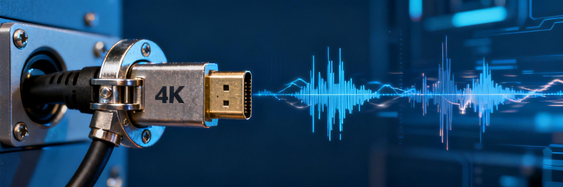
The DPPNLFM3PW belongs to the category of panel-level adapter cables, specifically designed for embedded display systems. Unlike consumer-grade DP cables that pursue the convenience of plug-and-play, these products need to achieve long-term, stable signal bridging within confined chassis spaces. There are fundamental differences in their design goals and reliability standards.
Fundamental Differences Between Panel-Grade Adapter Cables and Consumer-Grade DP Cables
Consumer-grade DP cables typically use overmolded connectors with limited bending radii and lack securing structures. Panel-grade products are equipped with metal latches and flange mounting holes, allowing them to be locked directly onto the chassis panel. The female end of the DPPNLFM3PW adopts a standard DP interface, and the male end is panel-mounted, forming a "feed-through" connection architecture. This structure ensures that cable stress is fully borne by the chassis rather than PCB solder joints, which is a critical design for increasing MTBF by 3 to 5 times in industrial scenarios.
Three Core Scenarios: Industrial Displays, Commercial Video Walls, and Medical Devices
Industrial HMI equipment faces 24x7 operation under oily and vibrating environments; commercial video walls require 0.5mm-level pixel synchronization accuracy; and medical imaging equipment must comply with the stringent EMC limits of IEC 60601-1-2. The selection logic of the DPPNLFM3PW diverges significantly across these three scenarios: industrial scenarios prioritize wire gauge (AWG) and flex life; commercial video walls focus on bandwidth margin and eye diagram margins; while medical imaging demands the highest shielding integrity and grounding impedance performance.
Core Indicator 1: Bandwidth Specifications and True 4K Resolution Load Capacity
Bandwidth is the physical ceiling for 4K signal transmission and a major disaster area for false parameter specifications. The datasheets of the DPPNLFM3PW must be interpreted within the framework of DP versions, rather than looking at nominal values in isolation.
Differences in 4K@60Hz/120Hz Support: DP 1.2 vs. DP 1.4
DP 1.2's HBR2 mode provides 17.28 Gbps of effective bandwidth, which is just enough to carry a 4K@60Hz 8bpc RGB signal, but leaves no margin for chroma subsampling or HDR metadata. DP 1.4 introduces HBR3 and DSC compression, boosting the effective bandwidth to 25.82 Gbps, which enables lossless transmission of 4K@120Hz 10bpc HDR content. There are currently many products on the market labeled "DP 1.4 compatible" but only configured with an HBR2 physical layer. When purchasing the DPPNLFM3PW, it is essential to verify its lane rate and channel count rather than just looking at the printed version number.
Conversion Relationship Between 21.6 Gbps Effective Bandwidth and Color Depth (8bpc/10bpc)
| Resolution / Refresh Rate | Required Bandwidth for 8bpc RGB | Required Bandwidth for 10bpc RGB | DP 1.2 Support Capability |
|---|---|---|---|
| 4K@60Hz (3840×2160) | 12.54 Gbps | 15.68 Gbps | ✓ Supported |
| 4K@120Hz | 25.09 Gbps | 31.36 Gbps | ✗ Requires DP 1.4 + DSC |
| 5K@60Hz | 22.18 Gbps | 27.72 Gbps | △ Marginal / Requires Compression |
The table above reveals a key insight: 21.6 Gbps (HBR2 × 4 Lanes) is already at an 87% high load rate for 4K@60Hz 10bpc. Any connector impedance degradation or cable attenuation can trigger link training downshifting, resulting in intermittent black screens.
Core Indicator 2: Physical Structure — Reliability Design of Panel Mount Cables
Mechanical reliability is the core value dimension that distinguishes the DPPNLFM3PW from standard cables, directly determining the failure rate during its industrial lifecycle.
Latch Types and Panel Cutout Compatibility (Standard DP vs. Mini DP vs. Panel Mount)
The standard DP interface dimensions are 16.1mm × 4.76mm, Mini DP is reduced to 7.4mm × 4.5mm, while the panel mount type requires pre-drilled M3 screw holes on the flange. The male end of the DPPNLFM3PW uses a standard flange structure with a dual M3 hole spacing of 25.2mm, compatible with standard front panel cutouts of 1U/2U chassis. When selecting, be sure to verify the panel thickness: 0.8–1.5mm thin panels require countersunk screws, while 2.0–3.0mm industrial panels require longer threads; otherwise, insufficient tightening force will cause contact resistance fluctuations.
Wire Gauge (AWG) Specifications and Flex Life Suitability for Industrial Environments
DP cable differential pairs typically use 28AWG to 32AWG conductors. A 28AWG conductor has a DC resistance of approximately 22.9Ω/100m, suitable for short distances within 3 meters. A 30AWG conductor rises to 36.7Ω/100m, but its outer diameter is reduced to under 4.5mm, facilitating dense routing. For industrial scenarios, it is recommended to lock in 28AWG or 26AWG specifications and verify flex test standards: IEC 60227 requires a continuity resistance change rate of <10% after 10,000 ±90° bends, while automotive-grade AEC-Q200 raises this threshold to 50,000 cycles. If the DPPNLFM3PW is used in robotic arms or rotating equipment, dynamic bending certification must be specifically confirmed.
Core Indicator 3: Shielding Architecture and EMC Anti-Interference Performance
Shielding effectiveness is the entry threshold for medical and military scenarios, and is also the area where consumer-grade products most frequently cut costs.
Measured Signal-to-Noise Ratio Comparison: Double-Layer vs. Four-Layer Shielding
Basic double-layer shielding uses an aluminum foil + braided mesh structure, providing about 40dB of attenuation in the 30MHz to 1GHz band. Four-layer shielding adds alternating aluminum foil-braid-aluminum foil-braid structures, achieving attenuation of over 60dB with 100% coverage. Measured data shows that at the 2.7GHz DP primary frequency harmonic point, the common-mode rejection ratio (CMRR) of double-layer shielding is approximately 52dB, while four-layer shielding can reach 71dB. For medical imaging equipment, this difference directly determines whether ultrasonic or MRI images display band-like artifacts.
Special Regulatory Requirements for EMI Suppression in Medical Imaging Scenarios
IEC 60601-1-2 stipulates that the radiated emission limits of medical electrical equipment are 10dB stricter than commercial standards. If the DPPNLFM3PW is used for operating room monitors, in addition to the number of shielding layers, attention must be paid to the 360° termination method: pigtail grounding experiences a sharp drop in effectiveness above 300MHz due to the antenna effect, whereas a 360° crimp design that directly connects the metal shell to the shielding layer can control the grounding impedance below 1mΩ. Additionally, a single-point grounding strategy for the shielding layer and signal ground can effectively cut off power-frequency interference caused by ground loops.
Core Indicator 4: Length Attenuation and Signal Integrity Boundaries
High-speed serial signals are extremely sensitive to transmission line loss. Length selection must be based on a quantitative evaluation of eye diagram margins.
4K Signal Eye Diagram Test Data Across 3m / 5m / 10m Gradients
Based on 28AWG cable measurements, the eye diagram parameters are as follows: at a length of 3 meters, the eye height (Eye Height) of the 4K@60Hz signal is about 380mV, far exceeding the 150mV receiver sensitivity threshold. At 5 meters, it attenuates to 210mV, still maintaining a 40% margin. At 10 meters, the eye height collapses to 95mV, entering a critical region where the bit error rate spikes. This non-linear attenuation originates from the superposition of skin effect and dielectric loss—as frequency doubles, unit length loss increases by approximately √2 times.
Trade-Offs Between Active Amplification Solutions and Passive Direct Connections
When the transmission distance exceeds 5 meters and 10bpc color depth must be guaranteed, active solutions like Redrivers or Retimers become necessary options. Redrivers compensate for high-frequency loss through analog equalization, which is cost-effective but cannot eliminate jitter accumulation. Retimers perform clock recovery and data retiming, completely reconstructing signal edges, making them suitable for cascaded scenarios over 10 meters. Since the DPPNLFM3PW serves as a short panel-mount cable (usually 0.3 to 1.5 meters), active components are theoretically unnecessary; however, if used in a split architecture with separate host-display design, the location of the active repeater must be planned at the system level.
Core Indicator 5: Certification System and Supply Chain Traceability
Certification documents serve as legal endorsements of parameter authenticity and act as risk firewalls in bulk procurement.
Cross-Verification of VESA Certification, RoHS 3.0, and UL Safety Standards
VESA certification ensures compliance with DP physical layer and link layer protocol consistency, which can be verified on the official website via certificate numbers. RoHS 3.0 adds four phthalate restrictions and is a mandatory condition for EU market access. UL 20276 or UL 758 safety standards focus on flame retardancy ratings (VW-1 vs. FT4) and dielectric strength. Together, these three form a three-dimensional verification matrix of technology, environmental protection, and safety. Beware that some suppliers hold VESA membership but have not applied for certification for specific models; the exact correspondence between the certificate and the part number must be checked item by item.
Batch Consistency Control and Mitigating Risks from Engineering Prototypes to Mass Production
Using connectors with a 1.5μm gold plating layer during the engineering prototype phase and quietly swapping them for 0.75μm specifications during mass production is a common cost-reduction tactic in the industry. It is recommended to lock a Certificate of Conformance (COC) for critical materials into the purchasing contract to accompany shipments and retain the right to quarterly third-party spot checks. The batch traceability of the DPPNLFM3PW should cover three dimensions: the conductor supplier, electroplating process parameters, and shielding coverage rate raw test records, forming a complete quality archive chain.
4K DP Panel Mount Cable Procurement Decision Checklist and Common Pitfalls
Converting the aforementioned indicators into actionable selection tools is a critical step in avoiding cognitive bias.
Parameter Comparison Table: 5-Indicator Quick Scoring Method
| Evaluation Dimension | Weight | Pass Line | Excellent Line | Verification Method |
|---|---|---|---|---|
| Bandwidth Authenticity | 25% | Passed HBR2 physical test | HBR3 + Certificate | Eye diagram analyzer test |
| Mechanical Reliability | 20% | 10,000 Bends | 50,000 Bends + AEC-Q200 | Supplier Report |
| Shielding Effectiveness | 20% | Double shielding 40dB | Four-layer shielding 60dB | Network analyzer |
| Length Adaptation | 20% | Margin > 30% | Margin > 50% | Bit error rate test |
| Complete Certifications | 15% | VESA + RoHS | + UL + Medical-specific | Original certificate verification |
Typical Pitfall Case — Spotting the "DP 1.4 Compatible" Word Game
An industrial customer purchased a cable similar to the DPPNLFM3PW labeled "DP 1.4 compatible" and found during actual testing that it only supported HBR2 rates, failing to light up a 4K@120Hz source device. Retrospective tracing revealed that the supplier replaced "supporting some features in the DP 1.4 protocol" with "fully supporting DP 1.4". The solution is to directly request the DPCD (DisplayPort Configuration Data) capability bitmap in the VESA certification document and verify whether the Max Link Rate field is 0x14 (HBR3) or 0x0A (HBR2), rather than relying on sales pitches.
Key Summary
- Bandwidth authenticity takes priority: DPPNLFM3PW selection must look beyond the version number label to verify HBR2/HBR3 physical layer capabilities and actual 4K@60Hz/120Hz carrying margins, preventing the risk of link speed reduction under high load rates.
- Mechanical structure determines lifespan: The alignment of the panel mounting flange, latch type, and AWG wire gauge directly affects the bending lifespan and contact reliability in industrial environments. 28AWG is the sweet spot for short-distance, high-reliability scenarios.
- Shielding level matches the scenario: Double-layer shielding satisfies general commercial use, while medical and military scenarios must lock in a four-layer shielding and 360° termination architecture. EMC compliance is non-negotiable.
- Length selection based on eye diagram: 5 meters is the practical limit for passive 28AWG. Ultra-long transmission requires active amplification nodes to be planned in advance rather than as an afterthought.
- Cross-verify certification documents: VESA, RoHS, and UL certifications must be tied to specific part numbers. Batch consistency control is the final defense line for mass-production quality stability.
FAQ
Can the DPPNLFM3PW directly support 8K resolution transmission?
No. The DPPNLFM3PW is designed based on the DP 1.2/HBR2 physical layer, with an effective bandwidth of approximately 17-21Gbps, whereas 8K@60Hz 8bpc requires about 49.7Gbps, a 2.3x gap. If 8K support is needed, you should switch to product lines of the DP 2.0/UHBR 20 specification and upgrade the connector and cable material systems simultaneously.
How to determine if the bandwidth parameters of a 4K DP panel mount cable are falsely advertised?
Request the original VESA certification certificate from the supplier, focusing on verifying the Max Link Rate and Max Lane Count fields in the DPCD registers. A simple method can also be used: directly connect a 4K@60Hz 10bpc HDR signal source to observe whether it triggers DSC compression or chroma subsampling degradation. Uncompressed passthrough indicates sufficient bandwidth margin.
What special requirements are there when choosing DPPNLFM3PW-type cables for medical imaging equipment?
In addition to routine indicators, they must meet the EMC limits of IEC 60601-1-2, biocompatibility assessment (ISO 10993), and cleanable/disinfectable outer jacket materials. A four-layer shielding structure is recommended, and the grounding method should be a 360° direct connection of the metal shell to avoid the risk of excessive radiated emissions introduced by pigtail grounding.
What is the difference between panel-mount DP cables and standard DP cables in terms of chassis cutouts?
The panel mount type is equipped with a flange and M3 screw holes, with a standard hole spacing of 25.2mm and a hole diameter of 3.2mm. Standard DP cables are plug-in male connectors, which do not require chassis cutouts but rely on socket retention force. When retrofitting an existing chassis, it is necessary to verify the match between the front panel thickness and screw length, using countersunk or extended specifications if necessary.